Self-driving Toycar: Difference between revisions
No edit summary |
No edit summary |
||
| Line 62: | Line 62: | ||
<pre> | <pre> | ||
Steering motor -> Shield M1 | |||
Steering motor | |||
Driving motor -> Shield M4 | Driving motor -> Shield M4 | ||
Car battery wires | Car battery wires -> Shield EXT_PWR | ||
</pre> | </pre> | ||
| Line 91: | Line 90: | ||
=== Connect the line sensor === | === Connect the line sensor === | ||
The line detection sensor module sends out short pulses of (invisible) infrared light and measures how much of that light comes back. | |||
It output the brightness/darkness as an analog voltage that the Arduino can use to steer the car. | |||
[[File:UNADJUSTEDNONRAW_thumb_15d9.jpg|500px|line sensor]] | [[File:UNADJUSTEDNONRAW_thumb_15d9.jpg|500px|line sensor]] | ||
| Line 117: | Line 120: | ||
=== Sensor testing === | === Sensor testing === | ||
* Test line sensor with: SDC_2_line_sensor_test.ino | * Test line sensor with: SDC_2_line_sensor_test.ino | ||
* Follow instructions in the file to find out the lowest and the highest values to distinct the line from the floor. | * Follow instructions in the file to find out the lowest and the highest values to distinct the line from the floor. | ||
| Line 126: | Line 130: | ||
=== Upload the car software === | === Upload the car software === | ||
* Open and upload SDC_3_car_test.ino | * Open and upload SDC_3_car_test.ino | ||
* Adjust the values | * Adjust the values | ||
| Line 131: | Line 136: | ||
=== Enhance the software === | === Enhance the software === | ||
* Test on the line and adjust values of speed or sensor if nessessary | * Test on the line and adjust values of speed or sensor if nessessary | ||
=== Tips === | === Tips === | ||
* It can help to remove the V9 battery when you upload the program to the arduino | * It can help to remove the V9 battery when you upload the program to the arduino | ||
* Make sure your sensor is close to the ground | * Make sure your sensor is close to the ground | ||
=== Ideas: === | === Ideas: === | ||
* Add ultrasonic sensor to avoid collisions | * Add ultrasonic sensor to avoid collisions | ||
* The car now always steers either left or right. Can we add straight ahead? | * The car now always steers either left or right. Can we add straight ahead? | ||
| Line 151: | Line 159: | ||
== External links == | == External links == | ||
* HC-SR04 ultrasonic sensor library. https://bitbucket.org/teckel12/arduino-new-ping/downloads | * HC-SR04 ultrasonic sensor library. https://bitbucket.org/teckel12/arduino-new-ping/downloads | ||
* L293D https://github.com/sudar/DCMotorBot | * L293D https://github.com/sudar/DCMotorBot | ||
| Line 156: | Line 165: | ||
Used modules: | Used modules: | ||
* https://www.hobbyelectronica.nl/product/l293d-motor-shield/ | * https://www.hobbyelectronica.nl/product/l293d-motor-shield/ | ||
* https://opencircuit.nl/Product/10540/TCRT5000-Infrarood-lijn-detectie-module-met-instelbare-gevoeligheid | * https://opencircuit.nl/Product/10540/TCRT5000-Infrarood-lijn-detectie-module-met-instelbare-gevoeligheid | ||
| Line 161: | Line 171: | ||
== Stuff that might need explaining? == | == Stuff that might need explaining? == | ||
* Digital and analog / Inputs and outputs | * Digital and analog / Inputs and outputs | ||
* What is an h-bridge? | * What is an h-bridge? | ||
Revision as of 17:15, 1 March 2017
Workshop manual
Team up!
- Form teams of 3-4 people
- Give your team a name!
Deconstuct the car
- Remove the screws to remove the top.
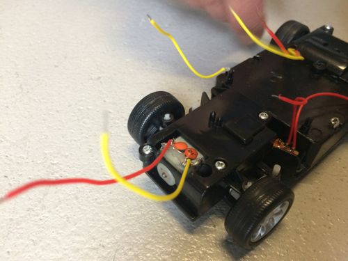
- Cut of all the wires going to the PCB, as close as possible to the PCB. (make sure the power switch keeps working and that it is off)
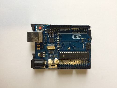
Test the Arduino and the Arduino software
Install Arduino Software
Open your first sketch
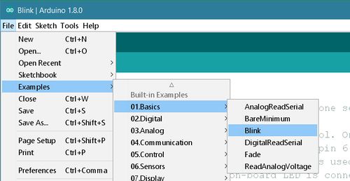
Open the LED blink example sketch: File > Examples >01.Basics > Blink.
Select your board type and port
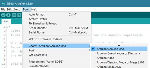
You'll need to select the entry in the Tools > Board menu that corresponds to your Arduino or Genuino board.
Select the serial device of the board from the Tools | Serial Port menu. This is likely to be COM3 or higher (COM1 and COM2 are usually reserved for hardware serial ports). To find out, you can disconnect your board and re-open the menu; the entry that disappears should be the Arduino or Genuino board. Reconnect the board and select that serial port.
Upload the program
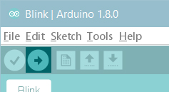
Now, simply click the "Upload" button in the environment. Wait a few seconds - you should see the RX and TX leds on the board flashing. If the upload is successful, the message "Done uploading." will appear in the status bar.
A few seconds after the upload finishes, you should see the pin 13 (L) LED on the board start to blink (in orange). If it does, congratulations! You've gotten Arduino or Genuino up-and-running.
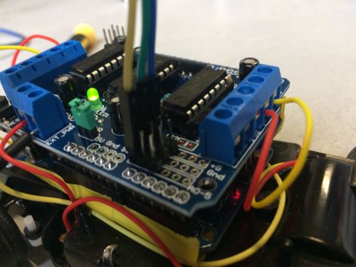
Connect the Motor Driver
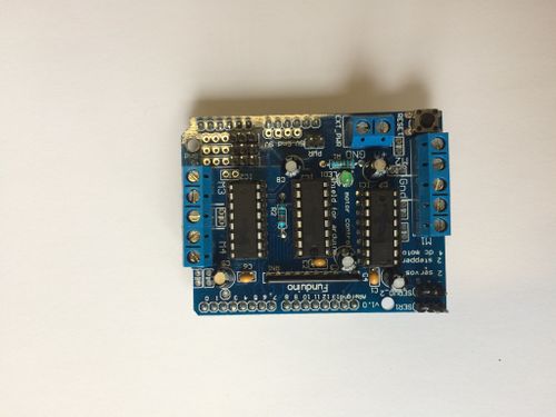
The Motor Driver or Arduino Motor Shield allows you to easily control motor direction and speed using an Arduino.
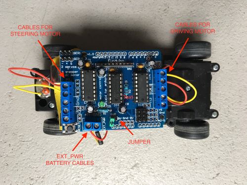
- IMPORTANT! disconnect the (green) jumper marked PWR right next to the screw terminal marked EXT_PWR
- Connect the shield to the Arduino
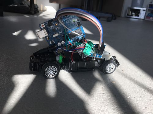
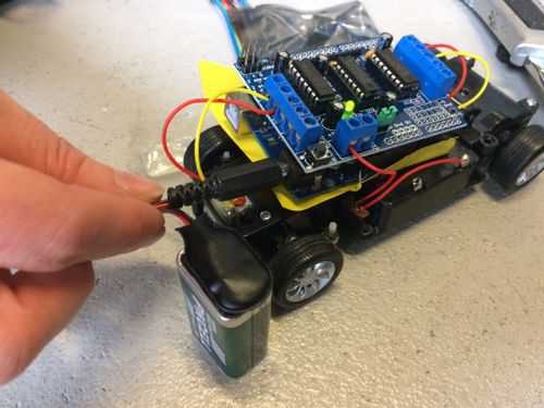
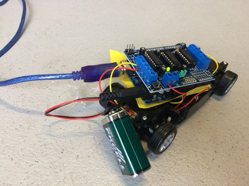
- Connect motor shield and Arduino to the car: Make sure motor, steering and battery cables are connected to the right outputs of the shield
Steering motor       -> Shield M1
Driving motor        -> Shield M4
Car battery wires    -> Shield EXT_PWR
- Cover the bottom of the Arduino with a piece of tape to prevent a connection of arduino with the battery (short circuit)
- Put the AA batteries in the car
- Connect 9 v battery to arduino, then connect the battery to the motor shield
Motors test over serial connection
- Connect Arduino to your computer
- We've prepared the example code for this workshop that you can download from GitHub: sample code
- After downloading the zip file from Github open SDC_1_motor_test.ino
- In Arduino go to "Menu" > "Sketch" > "Include library" > "Manage libraries" > search for "Adafruit Motor shield V1 firmware" and add
- Test if the Motor Shield works correctly by opening the Serial Monitor (magnifying glass, right hand corner)
- Test if direction and steering works as expected
- Change the cables on the Motor Shield if necessary
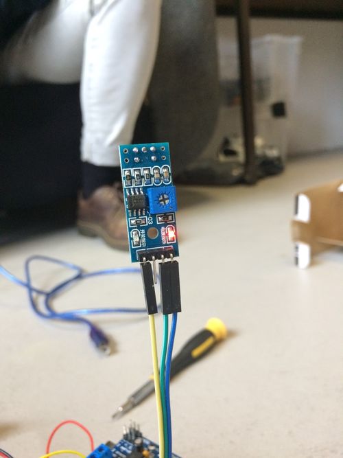
Connect the line sensor
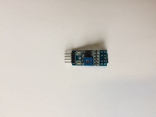
The line detection sensor module sends out short pulses of (invisible) infrared light and measures how much of that light comes back. It output the brightness/darkness as an analog voltage that the Arduino can use to steer the car.
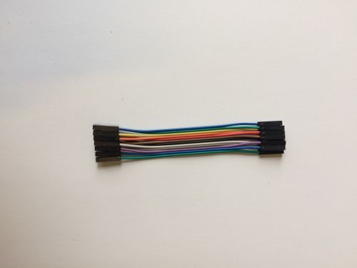
- Take 3 cables, put it on the sensor, look carefully at the colours and connections (A0, GND, VCC)
- Connect to the Arduino/Motorshield to the sensor
Module  ->    Arduino
- - - - - - - - - - -
VCC     ->    5V
GND     ->    GND
A0      ->    A0
- Connect the line sensor analogue output to A0.
Module  ->    Arduino
- - - - - - - - - - -
GND -> GND
VCC -> 5V
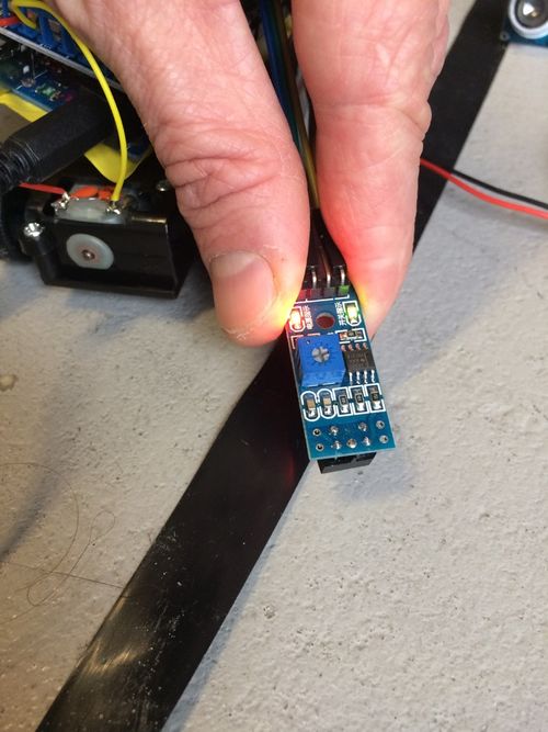
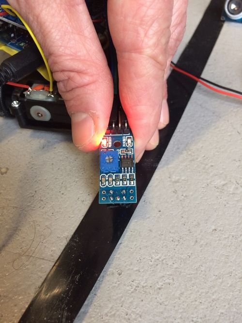
Sensor testing
- Test line sensor with: SDC_2_line_sensor_test.ino
- Follow instructions in the file to find out the lowest and the highest values to distinct the line from the floor.
Upload the car software
- Open and upload SDC_3_car_test.ino
- Adjust the values
- Upload the sofware to the Arduino
Enhance the software
- Test on the line and adjust values of speed or sensor if nessessary
Tips
- It can help to remove the V9 battery when you upload the program to the arduino
- Make sure your sensor is close to the ground
Ideas:
- Add ultrasonic sensor to avoid collisions
- The car now always steers either left or right. Can we add straight ahead?
- Try to make the steering proportional to the error in the line sensor
- Make the light sensor trainable. (Maybe add a button to switch between training / driving mode?)
Notes
- Spare batteries!
- Rubber bands!
- Tape!
- Soldering irons!
External links
- HC-SR04 ultrasonic sensor library. https://bitbucket.org/teckel12/arduino-new-ping/downloads
- L293D https://github.com/sudar/DCMotorBot
Used modules:
- https://www.hobbyelectronica.nl/product/l293d-motor-shield/
- https://opencircuit.nl/Product/10540/TCRT5000-Infrarood-lijn-detectie-module-met-instelbare-gevoeligheid
- https://opencircuit.nl/Product/10037/Ultrasonische-afstands-detectie-module
Stuff that might need explaining?
- Digital and analog / Inputs and outputs
- What is an h-bridge?
