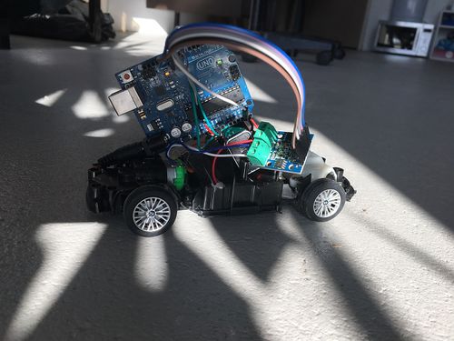
Self-driving Toycar: Difference between revisions
No edit summary |
No edit summary |
||
| Line 8: | Line 8: | ||
== Workshop manual == | == Workshop manual == | ||
=== | === Deconstuct the car === | ||
* Remove the screws on the bottom and remove the top. | * Remove the screws on the bottom and remove the top. | ||
* Cut of all the wires going to the BCP, as close as possible to the PCB. (make sure the power switch keeps working and that it is off) | * Cut of all the wires going to the BCP, as close as possible to the PCB. (make sure the power switch keeps working and that it is off) | ||
=== | === Connect the Motor driver === | ||
* Connect the motors to driver/h-bridge. <br> (Add diagram with pin names. Dependent of which driverboard we're going to use.) | * Connect the motors to driver/h-bridge. <br> (Add diagram with pin names. Dependent of which driverboard we're going to use.) | ||
| Line 20: | Line 20: | ||
Test > Sample code to test motors over serial connection. | Test > Sample code to test motors over serial connection. | ||
=== | === Connect the line sensor === | ||
Connect the line sensor analogue output to A0. | Connect the line sensor analogue output to A0. | ||
Revision as of 16:29, 19 February 2017
Soon you will find here a step by step guide towards a self-driving toycar!
What is exactly we want the participants to learn in this workshop? Do we have learning goals? It is going to involve some electronics/hardware knowledge(voltages/currents, wiring, h-bridge, infrared sensor, ultrasonic), some arduino and some pseudo code maybe. I am just curious how deep we want to go into any of these topics...
Workshop manual
Deconstuct the car
- Remove the screws on the bottom and remove the top.
- Cut of all the wires going to the BCP, as close as possible to the PCB. (make sure the power switch keeps working and that it is off)
Connect the Motor driver
- Connect the motors to driver/h-bridge.
(Add diagram with pin names. Dependent of which driverboard we're going to use.) - Connect the cars' battery to the driver
- Connect (solder) the driver ground to Arduino ground
Test > Sample code to test motors over serial connection.
Connect the line sensor
Connect the line sensor analogue output to A0. GND -> GND VCC -> 5V
Stuff that might need explaining?
- What is an h-bridge?
